Instruments, Controls & Dashboard
Note: I've started work on the implementation of my ideal instrument display, using an OLED display and HTML5.
Another option would be to forgo physical instrumentation completely and to use a head-up display but, this isn't realistic in a car designed mainly for use with an aeroscreen.

| The instruments in my Fisher Fury R1 are based around a DigiDash2 Lite by ETB instruments. This is a very good, compact, reliable, well priced, and IVA compliant system, covering all the main features required, along with some basic data logging capability. |
Having used it for 7 years, I have noticed a few things that I would do differently in my next car:
- I prefer an analogue speedometer and tachometer (rev counter), or at least a digital representation of them.
- I prefer permanent display of some information, such as fuel level, oil pressure, oil temperature and water temperature. On the DigiDash these are available by cycling through the various display settings.
- As well as a neutral indication, it would be good to have a permanent display of current gear selected too. I'm not sure if this is something specific to bike-engined cars but, the gears are very close together and it is sometimes difficult to judge which gear you are in.
- The design has to work both during the day and at night. I find it just amazing how so many car dashes light up like Christmas trees in the dark. It's incredibly distracting. It also needs to remain clear in bright sunlight.
- Blue lighting is definately not an option. Some cars (e.g. later Lotus Elises) have blue lighting but, it has the effect of blurring the vision on many people, myself included.
I do like the progressive shift lights on the DigiDash. The 'aux' light has been configured up as a neutral indicator on my Fisher Fury R1. There is no low oil pressure warning light but, this comes up on the main display as 'OIL'. I would prefer this to be a separate digital display that flashes when low.
I plan to design and build my perfect dashboard and instruments this time around, with no compromises on cost grounds. There are a number of factors driving this:
- Simplicity and light-weight - I plan to choose the optimum method for displaying each piece of information and the optimum components to achieve this.
- Efficiency in conveying important information - I plan to chose the most efficient method of displaying information, using both digital and analogue methods where appropriate. Whilst digital displays are very good at displaying static information, moving needles convey both value and direction for dynamic information information, such as speed and engine speed.
- Clarity and understanding - I plan to colour code the display of information with white fonts and lights for labelling, green for safe values, orange for warnings and red for alerts.
- As I'm using a digital display, I'm assuming I can also display text warnings too, e.g. "Front left tyre pressure is 13psi", "Water temperature is too high", etc.
This car will have no center console, just a shallow dash running across the front of the car.
Dials & Warning Lights
There are some things that simply work better as dials in my view. This doesn't mean that they have to be fully analogue though and a digital rendering of an analogue dial should be just as good as the real thing, given enough pixels. It also has some advantages in terms of clarity, colour and behaviour.
A pair of 80mm diameter dials would be about the right size for my chosen steering wheel. I much prefer white text on a black background and find this combination much more legible. White dial needles don't stand out enough in my view. My current preference is for green.
Speedometer
This needs to be displayed as a needle and gauge on a dial in my view. I've found the digital speed display on my DigiDash to be frustrating and it also doesn't stay constant when cruising on a dual-carriage way or motorway.
In my preferred design, the speedometer runs from 0mph to 140mph. Because I plan to render it in software, I will have the needle turn orange above 70mph and red above 100mph.
Tachometer
This also needs to be needle on a dial in my view. In this car I'm aiming for a rev limiter at 14,000rpm. This also nicely mirrors the speedometer that runs up to 140mph. It's a small thing but, I like this symetry.
Again, because it is rendered in software, the need will change colour, turning orange above 12,000rpm and red above 13,000rpm.
Shift Warning Lights
I really like the system used on the DigiDash with its dual, five incremental lights and then the main shift light. I have these configured with a 200rpm increment, up to the 11,500rpm rev limiter and this works really well. On the DigiDash the lights go from green to orange and finally to red and this kind of makes sense. The final red shift light needs to be lit before you hit the rev limiter!
I actually think a few more lights and a little bit more warning would be a good idea as in the first few gears the engine speed rises very quickly. My planned implementation will allow me to configure the engine speed at which each light illuminates and be able to set these differently for each gear selected. This is very useful because engine revs rise much quicker in 1st gear than tehy do in 6th!
My design has a single central sequence of six 'lights' implemented in software, three green and three orange. The final red light is an ultra-bright LED mounted above the display. This is simply to ensure that it can't be missed.
Mileometer
This is required for the IVA. This is clearly displayed on the display unit.
Trip Meter
Still not sure if I want this feature.
Current Gear
In a bike-engined car it is often useful to know which gear you are in and the gears are very close together, making it hard to determine the gear based on engine speed. This is more even true because of the 1-down, 5-up sequential gearbox. It is also very handy to know when the engine is in neutral and many won't start if this is not the case (though I've configured my Fisher Fury R1 to start in any gear). A current gear indicator on permanent display removes the need for a neutral light, though this is usually a digital signal direct from a bike engine.
Lights On
Not sure if this is required for IVA but, it is a useful indicator in a car with no doors (no reminding buzzer on exit) and it needs to operate when the ignition switch is off as well. A steady green light.
Handbrake Warning
This is required for the IVA. This line will also go to the data logger.
Comms
A visible indication that the in-car comms is transmitting.
Manual Fan Over-ride
It is a good idea to manually be able to control the electric cooling fan. This is useful for the IVA, MOT and emissions testing and when stuck in traffic on a hot sunny day. I have a switch on the dash of my Fisher Fury R1 to enable this.
The warning indicator will be green when the fan is on due to the thermostat and will be orange when the manual over ride is operated. The fan on/off status will also be captured by the data logger.
Fog Light
Required for IVA. Typically an orange light but given that the fog light is never likely to be used, it could be any colour!
High Beam Headlights
Required for the IVA. Typically a bright blue light.
Fuel Gauge
It is all very well having a digital fuel gauge on the Fisher Fury R1 but it is far from linear and it varies by quite a lot depending on whether you have been accelerating or braking. A percentage reading implies more accuracy than is realistically possible. An indication of miles remaining is often useful.
Oil Pressure
This needs to be a digital readout on a bike-engined car as it varies from about 10psi to 63psi on my Fisher Fury R1, depending on engine speed and oil temperature. I want a numeric value that is green when in range for a given engine speed and oil temperature, changes to orange when close to a set threshold and red when out of the defined range.
Oil Temperature
This needs to be a digital readout as you can gain value information from a bike engine installed in a car. I want a numeric value (ºC) that is green when in range, changes to orange when low or close to a set threshold and red when above a set threshold.
Water Temperature
This needs to be a digital readout as you can gain value information from a bike engine installed in a car. I want a numeric value (ºC) that is green when in range, changes to orange when low or close to a set threshold and red when above a set threshold.
Tyre Pressure Monitoring
I plan to have integrated tyre pressure monitoring.
The Solution
There is a certain set of information that you need to have on view in a bike-engined car. My plan is to have an digital display for the following information. This technology works well in all lighting conditions.
Taking all of the above into account, this is my current ideal design layout for the main instruments displays in my next car. I features two for the speedometer and tachometer. Both use a wide arc from 0 to 140mph/14,000rpm with 70mph/7000rpm being at the top. These are both linear dials and both feature major tic marks at each number. The speedometer also features minor tic marks for each mph. The gear indication sits within the tachometer. The odometer sits underneath both dials and is id dedicated to this purpose only. Between the two dials is are the incremental shift lights. Each light is fully programmable.
As you can see, this results in a very clear and simple display of the key information. The design of these are covered is detail in the electronics section. Whilst I've used text for the 'warning lights', these are likely to be replaced by graphics later.
I've recently purchased a Google Nexus 7 tablet with a 1280 × 800 pixel 7" display. I'm going to use this to test out the ergonomics of my design. The other thing I like about this approach is that swapping over from mph to kmh is a simple thing to do with software and would make life easier when abroad.
Prototyping
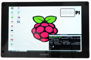
| I have ordered an HDMIPi to do some prototyping on. This is a 9" 1280 × 800 pixel display with HDMI input. |
3rd Party Examples
I've seen a number of 3rd party products and solutions that are quite close to what I'm trying to do:
GEMS sell a product to buuild you own bespoke instruments on a screen but, the resolution is quite low.
Virtual Dash for Car-PC is an open source project to create in-car instrumentation.
Switch Gear

| I used very high quality, waterproof switches in my Fisher Fury R1 and I'm really pleased with the way they have performed. The appearance might not be to everyone's liking but they are small, very light and have a nice tactile feel. The only thing that lets them down is the dash material on which they are currently mounted. It is simply not stiff enough and this will be rectified in both cars. The switches are available in black and several other colours, as well as in momentary or latching form. [3.6g] I've since discovered that these switches are used on quite a few race cars including the BAC Mono. I plan to move some of the switches around in my next car and maybe also in the Fisher Fury R1, when I update the dash. These switches have a 12mm panel cut-out. |
Ignition Switch
I wanted to use something clever here with key-less ignition but, these devices require a power source and because this car will use a very light, low-capacity battery, I don't want anything left connected to the battery when the car is not in use. This means a simple but quality ignition lock with a key will be used again.
Engine Start

| I'm using this sealed, vandal resistant, stainless-steel switch. This is a momentary action switch. [25.3g] |
Indicators
In the Fisher Fury R1 I have used an on-off-on toggle switch on the dash, to the left of the steering wheel. This works but, it is a bit of stretch to reach it. It is also a high current switch because it has to handle direct power to the indicators.
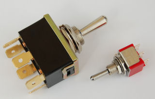
| I used a DPDT (double pole, double throw) centre off toggle switch (Maplin part no. JK30H) as this is solid and has a nice feel and positive action. It's a big switch. [32g] |
I now plan to use a SPDT (on-off-on) low current switch mounted directly to the paddle shift, using a 3D printed mounting. I can do this because of the clever electrical circuit design used, which ivolves very low currents only.
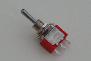
| The 3D printed switch housing was designed for this SPDT on-off-on switch (Maplin part no. FH01B). The contacts are rated at 5A 30Vdc but, in my design they will be switching very low currents. [5.2g] |
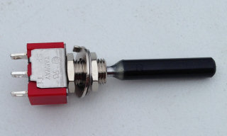
| This is the same switch after the toggle extension has been added. [5.5g] |
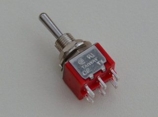
| The 3D printed switch housing was designed big enough to also accept this DPDT on-off-on switch (Maplin part no. FH05F) but, I'm not planning to use this in my car. [6.3g] |
Indicator Lamps
I plan to standardise on 5mm 'top hat', clear, LEDs for the indicator lamps. To save weight, there are two green LEDs directly mounted through the carbon fibre dash, into a 5mm hole. They are mounted so as to be flush with the dash front and thus almost invisible when not lit. These are mounted above the display panel and I've done it this way because the hazard warning lights have to operate when the ignition is switched off.
Hazard Light Switch
This will be latching push-button switch to match the others (as shown above). The wiring and design for this is covered in the electronics section.
Steering Wheel
This is covered in the steering section.
Horn
Based on my experience with the Fisher Fury R1, this needs to be a momentary action switch mounted on the steering wheel.
Pedals
The Fisher fury is quite a narrow car and the cockpit is cramped, when compared to 'normal' cars. This is largely due to the wide centre tunnel running down the car. The reality of this is that I can only really drive my Fury whilst wearing my Puma Speedcats. Even my normal trainers are a bit too wide to feel comfortable with the pedal arrangement. To some, this would be a compromise too far but, I've never considered it a real problem. Having said that, I plan a much wider footwell in this new car, with better pedal locationg, spacing and a foot rest to the left of the clutch pedal.
I didn't know any better when I built my Fisher Fury R1, so I used the standard pedal box supplied by The Kitcar Workshop. This was a mistake as it is very heavy and not very good quality. It is perhaps the lowest quality component on my car. This time around I plan to fabricate a well engineered and much lighter unit with all three pedals floor mounted.
Accelerator
Accelerator pedal is mounted from above the footwell in my Fisher Fury R1. My thinking is that it is best to keep all three pedals as part of a single, floor mounted unit that can be adjusted.
Brake Pedal
The brake pedal is covered in the brakes section. The mounting point behind the pedals for the brake master cylinders needs to be very rigid so that it doesn't flex. It will have an adjustable bias bar, with remote adjustment knob.
Clutch Pedal
Clutch pedal configuration will very similar to the configuration used in my Fisher Fury R1. One thing that I will do is provide the ability to adjust the cable mounting points, so that the gearing can be optimised. The clutch also needs an adjustable stop, to ensure the clutch cable is not pulled too far. This causes problems asuch as clutch 'lock out' on bike engines.
Handbrake
The handbrake is covered in the brakes section.
Paddle Shift (Gear Shift)
On the Fisher Fury R1, I have used a push-pull paddle system mounted to the column, which rotates through the centre of the column. With the relatively small steering wheel and quick ratio steering rack this has worked fantastically well. I would struggle to go back to a normal gear lever in a sports car now. It is so much safer and quicker as you don't need to take you hands off the wheel to change gear.

| I initially used a direct rod linkage system as shown here but, this proved unreliable (without resorting to 'heavy' engineering) and if anything, there was too much coming back through the paddles. I tried several configurations and had several failures before I gave up and moved to a push-pull cable arrangement. This is much lighter, provides great feel, whilst isolating you from the worst of the vibrations. A floating arrangement, with the engine end mounted on the engine itself, isolates the paddles from any engine movement, which is significant when performing rapid gear changes under hard acceleration or deceleration. The other thing to note in this diagram is that the pivot point of the paddles is set back from a line through the paddles themselves. This is not good as it means they also move sideways, when pulled. Although not a huge issue, it doesn't quite feel right. In my Fisher Fury R1, the pivot point is not offset like this. |
Mounting
The gap from the back of the steering wheel to the face of the paddle is currently 55mm in my Fisher Fury R1. This is mainly due to the Sierra column used. My paln is to reduce this distance to just 30mm and this will make the paddle much more comfortable to use. This is close as I can get given the depth of the steering wheel boss and the fact that the paddle must not touch the steering wheel in operation.
Fabrication

| My preferred solution is to use the billet allow paddle shift mechanism developed by Andy Bates. I've now had this installed in my Fisher Fury R1 and it is just brilliant. It is rock solid and fully adjustable to address the issues mentioned above. |
Paddle Shift Cable
The cable arrangement, gives you plenty of feedback and a wonderfully direct and weighted connection but, prevents the worst of the bangs, clunks and vibrations coming back through the paddles. It has proved very reliable in operation and is a light-weight solution too.
The move from front-engined to mid-engined means that a longer cable is going to be needed. To minimise the additional weight, I'm planning to use a short push-pull cable to operate a sliding 8mm carbon fibre tube down the length of the car, which is then picked up by another short push-pull cable in the engine bay. This should mean the additional weight is less than 700g.
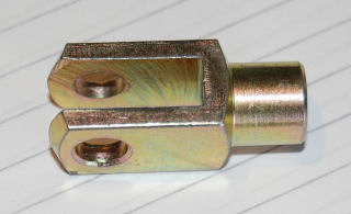
| The cable is mounted to the paddle shift via a 6mm clevis bolted to the paddle (6mm bolt). It is mounted with a 100mm offset from the centre of the steering wheel, as this gives the best balance between effort and feel. With a carbon fibre paddle, the clevis could probably form part of the paddle structure. |
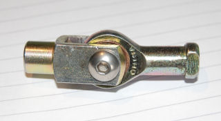
| I had to use a file to widen the jaws of the clevis a tiny bit, to enable the 5mm rose joint on the end of the cable to fit within it. A 5mm bolt holds it together. This is as light as I could make it and still keep it reliable. The parts shown here weigh 35g. |
Electronic Paddle Shift
The other option I am investigating is a fully electronic shift operated by the paddles and switches. I'm worried that I would miss the feel though and it may also add weight. The advantage of this approach are much quicker gear changes but, this car is not about headline numbers and the focus is on driver involvement.
Rear View Mirror
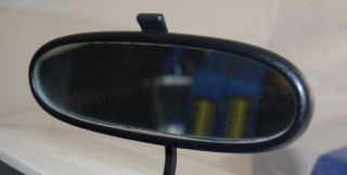
| I used a standard Mk I Audi TT oval rear-view mirror (the non-electric version) on my Fisher Fury R1 and it works really well apart from the fact that it is mounted on top on the bodywork above the dash and this is not rigid enough. The Audi TT mirror base is 108g and I cut it down, to reuse just the metal mounting ball, which conveniently has a hole through it. As my view current is slightly affected by vibrations, I'm planning a more rigid mounting point. The ability to dim the mirror is something I've never used and it won't help much as it is mounted upside down. This mirror is E-marked and I picked one of these up on eBay for just £15. |
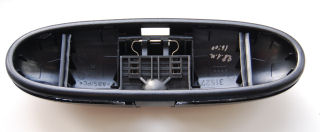
| The ball/base part that sticks to the windscreen is 108g on its own. The actual mirror part is 186g including the glass. |
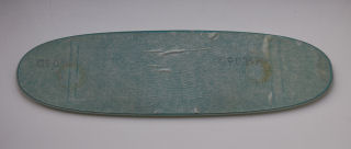
| My plan was to use 3D printing to make a light-weight custom housing for the mirror glass element only but, having unclipped the mirror housing, the glass element inside accounts for 102g (of the 186g) alone, so it is not worth the effort. |
Time spent recently with a mkIV Mazda MX-5 highlighted the value of an electronic auto-dimming rear view mirror and I'm going to investigate to see if I can find one suitable and light enough.
Side Mirrors
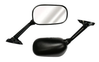
| I honestly don't think I'd find anything better engineered, lighter or more usable than the Suzuki SV650S/GSRX750 (part no. Toyo 000457) mirrors I used on a Fury. They offer a very good, clear field of view, and are resistant to vibrations. They are reasonably priced and road legal. They also offer little in the way of drag, having been designed for speed in excess of 180mph. |
Data Logging
Covered in the engine cooling system and the cockpit heating and cooling. This is because the engine and components are at the rear of the car and cockpit heating and cooling is at the front. It is to also remove any dependencies and to minimise weight.
Tyre Pressure Monitoring
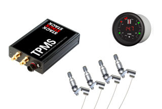
| I would like to add this capability for use on road and track but, I'm worried about the additional weight it would add to the car. Systems like the Stack TOMS also allow temperature monitoring too. |
Dashcam
This car will have an integrated dashcam with 1080p forward and rear facing cameras. The reasons for this are covered in the
The dashcam capability will be exposed in the car via 4 switches and associated 4 indicators:
- Black latching power switch + green LED indicator - this allows the device to be disabled.
- Blue momentary power switch + blue LED indicator - to select parking mode and to indicate parking mode enabled.
- Orange momentary recording switch + orange LED indicator - to select normal recording mode and to indicate recording in progress.
- Red momentary event switch + red LED indicator - to manually force event capture and to indicate event captured.

