 |
 |
|
 |
 |
|
 |
 |
|
 |
 |
|
 |
 |
|
 |
 |
|
 |
 |
|
 |
 |
|
 |
 |
|
 |
|
 |
Last page update was 06 Sep 2006 |
 |
|
 |
Fisher Fury Build Progress - December 2005
1st December
Revised Schedule
So here we are at the start of another month and my original list of jobs to do this side of Christmas looks a lot shorter and a little less daunting but, I have had to revised my targets in line with the dates for the exhaust manifold fabrication. The main unknown is when my half-shafts will arrive.
The revised targets are:
- Get the car ready to go to the manifold fabricators for 16th Jan 2006.
- Get the engine running by the end of February 2006. I'm not sure how long it will be with the fabricators but this date may come forward.
- Get body work on and car ready for track testing by end of April 2006.
- Get car SVA'd by end of May 2006.
Jobs To Do This Month
Fit rear suspension and uprights.
I need the remaining suspension bits (rear upper wishbones, front rocker spacer) from Martin.
I need the half-shafts to complete this. They are on order from The Kit Car Workshop  .
.
Fit half-shafts and hubs.
Fix brake pipes and associated brass work to chassis.
Fit front brake calipers and Goodridge hoses.
Fit rear calipers and Goodridge hoses.
- Clean front disks and fit front brake pads.
- Clean rear disks and fit rear brake pads.
- Fit handbrake cables to rear calipers.
- Bleed brake system.
- Fit the fuel pipes.
- Fit the fuel tank:
Need to fabricate some mounting straps.
- Get mounting straps powder coated and foam line them.
- Need to fit the fuel level sender.
- Fuel pump and filter fitted:
- Fuel pump wiring.
- Need to fabricate pump and filter mounts.
Fit exhaust silencer:
Need to fabricate a mounting bracket and check positioning with Martin to ensure it will sit within the side pod.
Fit wheels and drop down to floor level.
Need to cut front studs or get some open wheel nuts.
- Put the engine in:
Fit oil temp and pressure plate + sensors.
- Final engine check over with Richard.
- Fit prop-shaft adaptor.
- Check prop-shaft alignment.
Fit mounts and bolt into chassis.
Book exhaust manifold fabricators for mid-Jan 2006
- Get the car to/from exhaust manifold fabricators:
- Get a tow bar fitted to my Mazda 6.
- Borrow/hire a trailer to get the car to the exhaust manifold fabricators.
3rd December
My panels are ready to be collected from the powder coaters.
The washers for my front rocker arms arrived from Fisher Sportscars  so I've put them on the car.
Fixed the Goodridge hoses to the front calipers and chassis. These could go in at various angles so I used the one that seemed to make the most sense. Will check this later. The hoses have banjo connectors at the caliper ends to make reduce the bending required but I'm concerned that these seem to go too far into the caliper.
Having looked at my fuel tank mounting brackets, I'm not convinced aluminium is strong enough to hold up a tank full of fuel so I've got some steel to fabricate some stronger ones. I think I'm also going to need some stops to stop lateral movement. If the tank can move to the left by 1" or more under cornering it will allow the return and vent fixings to hit the chassis and snap.
Finished fabricating the radiator top mounts.
Drilled a hole for a rivnut to hold the T-piece midway between the front wheels. The ideal route for the brake pipes seems to be one that involves one smooth gradient, to avoid air locks. Cut and bent brake pipes from T-pieces to Goodridge hoses. Not sure about the route from the cylinder to the t-piece as it goes past an engine mount. Need to check this.
Also cut brake pipe along car and started to bend and drill the rivet holes for the rubber lined p-clips. Also started to rivet fuel lines into place. Can't rivet any brake pipes until I've put the nuts on and the flares on the pipes.
No more pictures for now as I've run out of hosting space :-(
4th December
Picked up my powder coated panels and put them out of the way for now. No point in fitting them until the brake and fuel pipes are fixed in place.

|
As I have to be quiet in the evening, I took the chance to get my mock dash fitted to the car and out of the way. This piece of MDF is simply to allow me to position the switches and DigiDash correctly and to relate the position of the switch gear to the rest of the wiring and the paddle shift. It's fitted via four M5 bolts and rivnuts along the bottom edge. I had to modify my original design slightly as the dash is narrower than I predicted.
|
7th December
My lower rear wishbones have arrived from The Kit Car Workshop  . As my half-shafts are on order I've taken a risk and booked my car in for the exhaust manifold fabrication. I've got a slot for mid January 2006.
Spent the evening putting the rear suspension and uprights on. Hit upon a problem though, in that the bushes on end of the upper swing arm are slightly too big (~1.5mm) to fit into the gaps on the rear uprights. I think the best way to proceed is to file down both sides of the bushes. Trying to bend the upper upright mount outwards looks impossible as it is very thick metal and this will damage the powder coat finish. I will check with The Kit Car Workshop  before I attempt to fix this.
The uprights are handed! The face of the rear upright faces forward and the kinked face towards the rear. If you don't get this right, the brake calipers will end up behind the rear wheels.
8th December
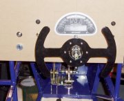
Paddle Shift Lever
|
Got the bolts for my paddle shift machined to a point, so I can now mount it properly. These clamp onto the column but because this is a fairly soft metal, I have two brass bushes fixed to the column surround. This works exactly as I'd expected.
|
Rear Upright Bushes
Spoke to The Kit Car Workshop  and filing the bushes down seems the best way to go to solve my problem. Filed about ½mm of each side and they fitted without problem.
9th December
Spent a little bit of time wiring up bits of the dash.
10th December
Rear Springs & Dampers
My Nitron NTR springs/dampers can go either way up. It makes more sense that the heaviest end is fixed to the chassis to reduce the unsprung mass. From what I can tell though, there is no heaviest end, so I planned to fit them with adjusters at the bottom on the back, where they are easier to reach.
I started with the rear and it was immediately obvious that, whatever way up they go, the chassis mount is going to hit the shoulder of the damper. I used an angle grinder to round off the corners of the mounts slightly. The other thing I found is that the powder coating within the bolt holes, makes it very difficult to get the bolts in. I needed a couple of washers to get a snug fit within the mounts.
15th December
Borrowed some hex sockets from Richard  so that I can get the engine sprocket off and try the adaptor for size. Also borrowed one to do up the rear hubs.
16th December
Spent the evening lowering the car closer to the ground so that I can think about getting the engine in and the wheels on. It's heavier than I expected. It also looks smaller nearer the ground. I'm now on holiday so hopefully I can make some better progress.
18th December
Started to look at the engine mounts because I want to see where the engine sits, to make sure the fuel pipes terminate at the right point in the engine bay and also to make sure that the brake pipes don't get in the way. Until the brake pipes are in at the front, I can't put the front springs/dampers in place.
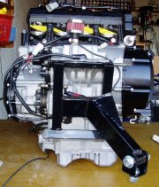
Engine Mounts
|
The first engine mount goes on easily enough but I had to spread the lower bars by a fraction to get it to fit.
I've got the original engine mounting bolts and spent some time finding suitable nuts (10mm fine thread), as mine were missing. It was time wasted though, as they are too long. I need an M10 x 180mm bolt at the top and an M10 x 200mm at the bottom.
|
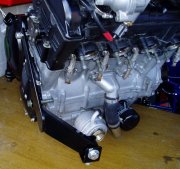
|
The second mount is going to need a 40mm spacer or a lot of washers to fit because the mounting faces on the engine are offset. The top bolt is going to need to be M10 x 40mm and the bottom one M10 x 80mm.
|
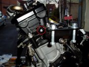
|
The third engine mount bolts to the chassis rail at the end of the footwell. I'm not sure if this will interfere with the bodywork though.
The main problem with this mount though is that the hole spacing does not match that of the engine as shown in the large image. The difference is about 5mm.
|
Sprocket Adaptor
How do you hold the sprocket still, whilst you undo the nut holding it on? I've not worked it out yet. I've tried Plusgas, putting the engine in gear but it just doesn't want to budge.
Radiator
Found some useful pictures on the web that show my radiator is probably mounted too high. I'd assumed this might be the case though and it is easy to adjust.
19th December
Started by having another tidy up in the garage. After a few days it gets hard to find my tools in all the clutter and debris.
Fuel Tank Straps
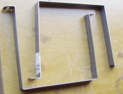
|
Using some 25mm x 3mm steel flat I fabricated my fuel tank straps. I bent them to shape using a vice and a hammer. I'm going to get these powder coated as they will be quite exposed. I can then stick the foam to them.
|
Exhaust Silencer
My Yamaha R1 silencer has a fixing bracket in the right place but I used an angle grinder to cut off the unrequired bits and to remove most of the inlet pipe. I used some 25mm x 4mm aluminium flat and some right angle to make a bracket to hold this in place. I riveted it at the bottom but could not get access to rivet the top, so I bolted through the chassis rail with a countersunk headed 5mm bolt.
The position of this is crucial as it has to fit inside the GRP side pod, which I don't have yet. The guidance from Martin was to mount it ½" below the side impact rails as close as the mount allows to the chassis.
Engine Mounts
Tried to get hold of an odd collection of bolts required to fit these properly and was partially successful. They are mainly unusual thread pitches though.
Discussed the poorly fitting engine mount with Martin via e-mail and although I could return it for one that is a perfect fit, time is against me and it is going to be much quicker to just elongate the hole to fit. Another time consuming job I could have done without.
Front Wheels
Trial fitted the front wheels but the front studs (which were ordered specifically to fit my Compomotive CXR wheels) are at least 20mm too long. As I've got closed end wheel nuts, they won't fit. I'm going to leave these for now but I've got two options; to cut them and use my existing bolts or to get some new open wheel nuts. I some how think that the studs will be too long to pass the SVA test though. I'm going to postpone my decision for now.
20th December
Today's objective was to finish the fuel system but, the plumber finally arrived so I got called upon to do my duty in the ensuite bathroom :-(
Fuel Pipes
I started fitting these to the chassis rails having checked the run from the engine to the fuel tank area. I'm using some aluminium brackets so that I can get a nice tidy run down one chassis rail. Had to be careful to keep away from the handbrake lever. I didn't quite finish this job.
Driveshafts

|
My drive-shafts arrived looking very shiny and new. These will have to wait until tomorrow but I checked that the drive-shafts and hubs all went together as expected. This means that a rolling chassis by Christmas is looking possible.
|
21st December
Driveshafts
Started with these, simply to get them on the car and out of the way. It seems to be the way of things when building a kit car in a single garage. I thought it would not take long!
First job was to put the studs in the rear hubs. These are 'interference fit' and just hammer into place. Sounds easy but, it took ages to get them to go in all the way. It was hardly worth painting my hubs. I tried a large vice but this simply was not going to do the job, so I resorted to the engineers tool of choice, a large hammer. Even this failed to do the trick until I found something suitably solid to rest the hub on (a very large piece of metal with a hole in the right place), whilst I hit the stud. Discovering this sooner could have saved me over an hour.
I checked the studs against a wheel and the layer of Hammerite on the hub means the wheel won't quite go on so I had to sand off the paint where it goes into the wheel. Even with the brake disks on, the rear studs are going to be too long for my CXR wheels too :-(
It's been a while since I took these apart so I referred to the Sierra Haynes manual for guidance. First you have to remove the old bearing outer races with a punch, being careful not to damage the hub carrier faces. Then I gently tapped in the new ones with a punch, making sure they went in square and seated nicely. Using lots of grease I then put the new bearing inner races in.
The seals are very delicate and a pain to fit but I noticed that the old outer bearing races sit perfectly over the rubber part of the oil seal and can be used to push them home, using a vice.
I pushed the drive shafts in to the diff and then put the spacer and hub carrier over the end of the driveshafts. I then bolted the hub carrier to the upright, noticing that the drive shafts compressed by about 15mm in doing this.

|
The last bit is to slide on the hubs, which are held in place with a washer and a large nut. I will leave the torqueing up of the shaft nuts till later, I have the hex socket to fit them but, nothing with a 3/4" square drive. The nuts are handed so that turning both of them in the direction of the wheels, whilst moving forward, will tighten them.
|
Track Rod End Adjustment
This requires the camber to be set up first because it alters the geometry. I adjusted the track rod ends to get roughly the right toe in for now (the front wheels are not parallel but point inwards slightly at the front). Fisher recommend that the front wheels should have a toe in of 3-4 mm. This is checked by measuring the distance between the wheel rims at the front most edge of the wheels and then the rear edge. I will get this set up properly later on with the rest of the suspension.
The distance between the rear hubs is about 10cm more than that between the front hubs, so I clamped a 2.4mm length of aluminium angle along the face of the front hubs and angled them until it pointed 3cm in from the face of the rear hubs (my toe in). This should also mean the car will drive in a straight line when the steering wheel is centred. I then adjusted the rod ends to match this front hub position.
22nd December
DigiDash 2 Lite
I bought this as part of a 'group buy' on the and it arrived today. It doesn't have the data logging of the DD2 Pro unit but I needed to save some money some where, to keep this project within budget. This is the one major compromise I've had to make so far in this respect but, I'm wiring my car up for the Pro unit, just in case I decide to upgrade at a later date.
26th December
Wheel Nuts
The simplest solution (and cheapest) to my wheel nut dilemma seems to be to modify the wheel nuts. The quick and dirty approach is to cut the ends off with a angle grinder. The best solution would be to put them on a lathe and to machine the ends down but, I won't have access to a lathe for another week or so. The angle grinder worked pretty well though!
28th December
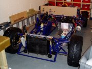
|
With the suspension all done I decided to fit the rear disks and wheels, to see how the car sits on them. This then allowed me to apply some decent torque to the rear hub nuts. I'm still not sure they are tight enough though.
Having got this far, I couldn't resist having a sit in my car :-) The steering is deliciously direct and responsive.
|
A quick check of the ride height shows the front at 130mm and the rear at 150mm (without driver). This is pretty much spot on the recommended road settings (127mm/5" and 152mm/6"). Without the engine in, I can easily pick up the front of the car and move it around.
30th December
Brake Pipes
I cut and bent the brake pipes to connect the various connectors and used a cam action flaring tool to provide the right ends (some convex, some concave). This was very easy using the quality tool I borrowed from my work motor club. The pipes were then riveted to the chassis at regular (100mm maximum) intervals, using rubber lined p-clips. I am missing the unions required from the outlet ports on the Girling master cylinders (3/8" UNF) so I can't fix these pipes yet. The .625 is the front and the .75 is the rear cylinder.
Rear Brake Calipers
Fitted rear calipers and Goodridge hoses. The rear calipers are mounted upside down, which puts the bleed nipple and inlet at the bottom of the caliper. Because the calipers are upside down, the bleed nipple and inlet need to be swapped over.
You need to put the Goodridge hose into the caliper before you fix it to the chassis, as it needs to rotate to go into the caliper. You can then rotate the hose in the chassis hole to make it twist itself away from the tyre. Even so, it seems a bit close to me. At this point I realised I haven't bought any rear brake pads :-(
31st December
Popped over to my local friendly motor shop (Eastern Auto Spares) and they will have some Sierra pads in for me later this afternoon. They gave me a union to try in my master cylinders but it is metric and far too big.
I popped a long to the sales in my local cooking shop to pick up a large plastic measuring jug, a sieve (to catch the sump bolt) and some funnels. Just what I need to drain the engine and fit the adaptor plate.
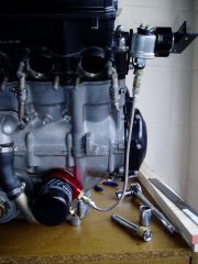
|
Fitted the adaptor plate for the oil temperature and pressure sensors. The pressure sensor needs to be remote from vibrations hence the flexible hose (temporarily tie-wrapped to the engine mount). This sensor has a proper earth connection which is handy (missing on earlier versions).
|
Picked up my brake pads and the chap had also found some suitable 3/8" UNF unions. Completed the front braking system on my car this afternoon. All I need to do now is to clean the disks and pop in the Elise brake pads. I've got all the bits needed to complete the rear brakes now but, I've run out of time to complete all of my goals for this month. I got very close though and have also done a few jobs that were not on my list.
Next month
 |
 |
|
 |
 |
|
 |
 |
|
 |
 |
|
 |
 |
|
 |
 |
|
 |
 |
|
 |
 |
|
 |
 |
|
 |
|
 |
Copyright © Robert Collingridge 2004 |
 |
|
 |


![]() so I've put them on the car.
so I've put them on the car.
![]() before I attempt to fix this.
before I attempt to fix this.
![]() so that I can get the engine sprocket off and try the adaptor for size. Also borrowed one to do up the rear hubs.
so that I can get the engine sprocket off and try the adaptor for size. Also borrowed one to do up the rear hubs.

