 |
|
 |
|||||||||||||||||||||||||||||||||||||||||||||||||||||||
 |
|
 |
|||||||||||||||||||||||||||||||||||||||||||||||||||||||
The transmission design is heavily based on the various ratios of the gearbox, the primary reduction ratio in the bike engine, the differential and the size of the wheels. I modified an Excel spreadsheet that I found on the web to calculate in-gear speeds for a given set of components. In fact I've got several versions of it, all based on Yokohama A048R 205/60R13 tyres on the back of my car:
I now have an additional page on the clutch.
The pedal on a car has more movement when compared to the hand-operated clutch on a bike. This means that the bike clutch feels very binary in operation when connected to a clutch pedal on the floor. You can fix the cable end closer to the pivot point to increase the pedal movement required but this has the effect of making the clutch lighter and reducing feedback. This is improved by uprating to a stiffer clutch spring. There are two main options:

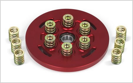
A Barnett clutch upgrade ![]() is available for the R1. If this kit is purchased, it should be noted that the stock clutch has only a single diaphragm spring which is discarded along with the pressure plate. The Barnett kit contains two sets of springs; silver (the stiffest) and gold (stiffer than the diaphragm spring but less stiff than the silver springs) with instructions to replace the diaphragm spring with gold (for street use) or silver (for racing) or a combination (for hard street use). On a bike the clutch is mechanically operated so stiffer springs would make for sore hands. In a car the stiffest springs are probably the best bet. Clutch demands in the car application are higher than any street bike can demand. The Barnett springs can be mixed (three silver and three gold) and the hold-down screws along with their individual spacers to match. The silver spacers (an insert into the inner coil of the spring) have been "turned" so they will go inside the thicker wire windings of the silver springs.
is available for the R1. If this kit is purchased, it should be noted that the stock clutch has only a single diaphragm spring which is discarded along with the pressure plate. The Barnett kit contains two sets of springs; silver (the stiffest) and gold (stiffer than the diaphragm spring but less stiff than the silver springs) with instructions to replace the diaphragm spring with gold (for street use) or silver (for racing) or a combination (for hard street use). On a bike the clutch is mechanically operated so stiffer springs would make for sore hands. In a car the stiffest springs are probably the best bet. Clutch demands in the car application are higher than any street bike can demand. The Barnett springs can be mixed (three silver and three gold) and the hold-down screws along with their individual spacers to match. The silver spacers (an insert into the inner coil of the spring) have been "turned" so they will go inside the thicker wire windings of the silver springs.
Update: I June 2013 I upgraded to the Barnett clutch. I now have an additional page on the clutch.
Richard ![]() changed the clutch spring plate for a 20% stiffer Yamaha engineering Corporation (YEC) race version. I know it works well, so I've gone down the same route. It may still feel lighter than a typical car clutch but I'll get used to it. The part cost me £61.95 inc. VAT from Orwell Motorcycles
changed the clutch spring plate for a 20% stiffer Yamaha engineering Corporation (YEC) race version. I know it works well, so I've gone down the same route. It may still feel lighter than a typical car clutch but I'll get used to it. The part cost me £61.95 inc. VAT from Orwell Motorcycles ![]() and the part number is 4XV-16334-70.
and the part number is 4XV-16334-70.
In June 2013 this was replaced for the above Barnett conversion. After 6 years of use, the plate had worn badly and lost a lot of its spring.
The Digidash is programmed to match measured engine rpm to measured speed (sensor/magnets on the propshaft) and deduce the indicated gear, which is then displayed on the unit.
My preference is for a paddle shift mechanism though. There are two ways of doing this:

|
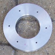
My chosen paddle shift mechanism is simple and light. I've got an aluminium ring (100mm OD, 50mm ID, 12mm thick) that goes over the steering column. This weighs 180g. It has two opposing, threaded holes through the outside edge. Two 6mm x 40mm bolts (machined to a 60° point) pass through these holes and clamp the ring to the column surround.
The column surround has two shallow 5mm locating holes drilled into it and bronze top-hat bushes sit within them. The bushes have a 2mm internal hole for the pivot bolt to sit in. The bushes are required to provide a hard material to seat the bolts into. The steering column surround is too soft an alloy for this type of arrangement. The bolts provide a rigid but freely rotating pivot for the mount. |
The two-cable solution uses two cables to provide a left and right pull/pull action, with the cables pulling against each other. The advantage of this approach is that it is very easy to do and would be very light as thin cables can be used. The down side is that it is going to lose some feel compared to the rod solution, something I'm not keen on. My car is all about being 'connected' to the driving experience.

|
The rod solution uses a single rod mechanism to provide a push/pull action. This picture shows the approach taken on the Stuart Taylor Race Phoenix |

|
The third option is to use a single, thick cable that is capable of a direct push and pull action. This is the approach that Chris |
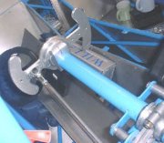
My design uses a series of rods and pivots.
This bolts onto the output shaft of the gearbox and provides a flange onto which the propshaft is bolted. On a motorbike this would have a chain sprocket. This is pretty much unique to each bike engine in terms of the splines and thickness required. It is important that the engine mounts place this drive flange, in the centre of teh car, to ensure minimal propshaft angles. Ideally this should be zero. This must be fitted with a locking washer and is torqued up to 85Nm (61lb-ft).
Fisher Sportscars ![]() can supply a short one-piece propshaft to connect the gearbox to the differential. It has two universal joints to allow flexing under power and a centre bearing. It's quite a heavy item. A benefit of a mid-engined car layout is that the propshaft would be very short and light. Richard
can supply a short one-piece propshaft to connect the gearbox to the differential. It has two universal joints to allow flexing under power and a centre bearing. It's quite a heavy item. A benefit of a mid-engined car layout is that the propshaft would be very short and light. Richard ![]() bought a custom made two-piece propshaft from Bailey Morris
bought a custom made two-piece propshaft from Bailey Morris ![]() for his Striker and they are default place people seem to go to for these things. The centre mounted bearing requires a custom mounting bracket/spacer to mount it at the right height.
for his Striker and they are default place people seem to go to for these things. The centre mounted bearing requires a custom mounting bracket/spacer to mount it at the right height.
Bailey Morris now do three types of centre bearing and prefer to sell the new, lightweight option. I clamped a steel rule across the centre tunnel, in the middle of the welded in plates for the centre bearing and used this as reference to measure the sections. From this point to the face of the differential is 768mm. From this point to the face of the engine output shaft adaptor is 520mm. These measurements are easy to make with a 1m steel rule. The engine output sprocket has 4 holes at 69.8mm PCD. The Sierra diff input has 4 holes at 90.0mm PCD.
I'm using a 7" Ford Sierra differential with push-in type tripod shafts. Richard ![]() used a 3.38:1 ratio differential. His 1998-2001 R1 engine had an 11,750 redline and he once saw 12,100rpm in 6th which was at about 133mph. 3.38:1 differentials are quite hard to find. You can use a bolt-on Lobra joint type diff because the internals are basically the same. If you undo the back plate and remove two circlips, the bolt on shaft mounts will slide out to reveal the splines you would find within a push-in shaft diff. The 7" Sierra differential weighs 20.1Kg.
used a 3.38:1 ratio differential. His 1998-2001 R1 engine had an 11,750 redline and he once saw 12,100rpm in 6th which was at about 133mph. 3.38:1 differentials are quite hard to find. You can use a bolt-on Lobra joint type diff because the internals are basically the same. If you undo the back plate and remove two circlips, the bolt on shaft mounts will slide out to reveal the splines you would find within a push-in shaft diff. The 7" Sierra differential weighs 20.1Kg.
The ratio of these differentials are marked on the a tag which is bolted via one of the backplate bolts (top left as looking from the rear). Most of the time these tags are missing or completely unreadable. You can check you have a diff with the right ratio by counting how many turns of the input shaft are required to make the output shafts turn once.
Fisher Sportscars ![]() use a Landrover Freelander differential in some of their kits with a 3.2:1 ratio. These differentials are claimed to 8kg lighter but this doesn't seem to be the case by the time you've added the Lobro joints. There is a small weight saving though. The downside, is the limited set of ratios available.
use a Landrover Freelander differential in some of their kits with a 3.2:1 ratio. These differentials are claimed to 8kg lighter but this doesn't seem to be the case by the time you've added the Lobro joints. There is a small weight saving though. The downside, is the limited set of ratios available.
For the 2006 chassis Fisher now supply machined spacers to simplify the fitting and to ensure the diff is now central for equally length driver shafts.
Ford axle codes(on the VIN plate): A=3.36 B=3.77 D=3.92 F=3.842 J=4.056 K=3.31 M=3.14 N=4.29 P=3.58 J=3.62 V=3.33 Z=3.59 2=4.27 3=3.62 4=3.82 5=3.26 6=3.12 8=3.56
3,14 CW47-Pin15
3,38 CW44-Pin13
3,62 CW47-Pin13
3,92 CW51-Pin13
3,77 CW49-Pin13 6.5 inch diff
3,38 fitted to 1,6 OHC ECO 5 speed
3,38 fitted to 2,0 OHC HC
3,38 fitted to 2.3 v6 ESTATE
3,14 fitted to 1,6 OHC ECO 4 speed
3,14 fitted to 2.3 v6 SALOON
3.14 fitted to 2.3 Diesel
85GG 4006 DC --- 3.97
85GG 4006 BC --- 3.62
85GG 4006 AC --- 3.38
85GG 4006 FB --- 3.36
87BG 4006 GB --- 3.14
86GG 4006 AAA --- 3.92 LSD
V87BB 4006 BAA --- 3.62 LSD
V87BG 4006 CAA --- 3.38 LSD
85GG 4006 AAA --- 3.36 LSD
Vin plate codes for Diff ratio:
Ratio Code
3.14 M
3.36 A
3.38 U
3.62 V
3.64 3
3.92 D
I needed to replace the differential oil seals before I installed my diff for the first time. These are hard work to get out and I used a claw hammer and a rubber mallet to lever them out. It took over an hour to do both sides! The right tools (which I now have) would make this job a lot quicker.
The Ford Sierra differential needs a GL-5 specification oil and most people seem to use the Red Line 70W75 ultralight shockproof gear oil ![]() on bike engined cars, as it has a lower viscosity. The oil is supplied in US Quart's (946ml). This is just about enought to fill the diff up to the required level (about 5mm below the filler/drain hole).
on bike engined cars, as it has a lower viscosity. The oil is supplied in US Quart's (946ml). This is just about enought to fill the diff up to the required level (about 5mm below the filler/drain hole).
The diff oil plug has a magnet to catch any metal parts in the oil and mine has always been clean with just a few tiny metal filings on it.
In my car, gaining access to the differential fill plug requires the fuel filter to be moved out of the way. The fill plug is almost half way up the diff and there is no drain plug, so I used my garage vacuum cleaner to create negative pressure inside a 5l plastic container and sucked the old oil out into this using some 8mm hose.
The centre hub nut is done up to 240lb-ft torque so it is best to undo them whilst still on the car. This can prove interesting in a breakers yard as quite often the cars are stacked.
These are 1.8CVH tripod type drum hubs to match the half-shafts. The push-in shafts always have drum brakes but, the hubs are interchangeable so you can fit disks and callipers to them. To convert to rear disk brakes the disks are simply clamped on to the hub by the wheel, but you need slightly (1") longer wheel studs. These studs are interference fit.
The shafts are handed and the left hand shaft has a anti-clockwise thread on it to prevent it working loose. New hub nuts are required on the shafts as they are done up to a 250lb-ft of torque. To be on the safe side I'm also replacing all the bearings and seals and these come as a kit with new hub nuts. The washers are seperate items.
The standard Sierra wheel bearings are used on the rear and bearing are supplied by Fisher Sportscars ![]() for the front pattern alloy hubs. The bearings need to be packed with grease and Castrol LM is a suitable high-temperature, lithium-based grease. Mobil Infinitec 152
for the front pattern alloy hubs. The bearings need to be packed with grease and Castrol LM is a suitable high-temperature, lithium-based grease. Mobil Infinitec 152 ![]() is a higher quality alternative.
is a higher quality alternative.
 |
|
 |
|||||||||||||||||||||||||||||||||||||||||||||||||||||||